

FAQ
Need advice? A problem with a product? Our FAQ is here to answer all your questions!
Filter by :
Connected pool
Connected electrical panels
All the appliances in our catalogue that are compatible with the Vigipool system are marked VP in their designation. Several examples of compatible appliances:
Zelia VP: salt chlorinator
Phileo VP: automatic pH control
tild VP: multifunction panel
Ofix Vp: Measuring chamber
Once connected to Wifi, your Vigipool devices are accessible anywhere in the world, as soon as you have an active internet connection on your smartphone (Wifi, 4G, 5G, etc.).
No, it's a free application that you can easily download from the Google store or App store. The application will remain free of charge, no matter how many devices are installed in your technical room.
The Vigipool universe is a range of connected devices. The Vigipool range provides access to the technical room from anywhere on earth. Devices compatible with the Vigipool system are connected via Bluetooth or the local Wifi network. Once connected to the Wifi network, the devices can be accessed remotely via the application as soon as you are connected to the Internet.
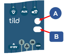
It may be necessary to reset the Tild VP to factory settings. There are two ways of doing this:
With upstream power failure:
1. Switch off power supply and wait ten seconds.
2. Press and hold button (B) on the unit.
3. Switch the unit back on, keeping the button pressed.
4. Wait for LED (A) to flash red rapidly.
5. Release the button.
All parameters are reset to factory settings.
Without upstream power failure :
1. Press and hold button (B) for approx. 10 seconds.
2. Wait for LED (A) to flash red rapidly.
3. Release the button. All parameters are reset to factory settings.
Connected analyzer
Like all devices that can be integrated into the Vigipool universe, the Ofix VP must be permanently powered. This allows them to be constantly connected to the WiFi network and to operate remotely. It comes with a male plug and transformer, so all you have to do is plug it into a 230V female socket.
If you don't have a 230V socket nearby, you can cut the power cable before the transformer and connect it to a suitable circuit breaker in your electrical panel.
Hydraulic installation of the Ofix VP analyser involves a single 20 cm cut in the pipe. All the components needed for the analyser to work properly are already built in: flow sensor and pH / ORP probes. The union fittings are then glued to the pipe and the unit installed.
The unit is fitted with a temperature sensor and should be installed before the heating systems, as close as possible to the filtration pump.
On initial installation, you will need to dismantle the Ofix VP analyser to either remove the pH / ORP probe caps or install the probes.
The Ofix VP, installed on the pipe, will play the role of a conventional measurement chamber, with real-time feedback to your application.
Your smartphone application will display the following measurements:
pool water temperature
measurement of water RedOx
measurement of water pH
This will allow you to automate the measurements, without the need for test strips, so you can adapt your manual water treatment.
You can upgrade your installation to an automated water treatment system by combining Daisy VP dosing pumps to regulate pH or ORP, or a Vigipool-compatible chlorinator.
Connected regulation
When setting up your device, if you select a daily limit value, the device will measure the volume of corrective product injected into the pool. If, over a period of 24 consecutive hours, the device injects as much as the configured limit value, it stops injecting the corrective product and causes the dosing pump to flash orange.
If no max. daily volume has been set, no measurement or alert is triggered.
The max. daily volume setting can only be set in the application.
All the color codes available on the Phileo VP are detailed in the following video:
Connected salt chlorinator
LED Lighting
LED light
Le nettoyage de la cellule doit se faire au moins 1 ou 2 fois par ans environ (au moins une fois en début de saison / remise en route de la piscine)
Procédure de nettoyage
- Désinstaller la cellule de la canalisation
- Boucher une extrémité à l'aide d'un bouchon (vous pouvez opter pour notre bouchon de nettoyage spécifique
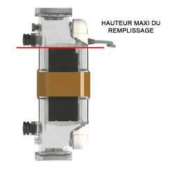
- Remplir la cellule par l'autre extrémité et la remplir d'acide dilué à 10%
Ne versez jamais d'eau dans de l'acide ! Toujours verser l'acide dans l'eau
- Arrêter le remplissage en haut des plaques en titane Et éviter tout débordement pouvant atteindre le connecteur
- Laisser agir puis vider la cellule et la rincer. Remettre en route la filtration sans brancher la cellule pour la rincer complètement.
(Anglais temporaire) Lors du raccordement de la régulation de niveau Niva 5, vous devez raccorder la marche forcée dans votre coffret électrique. Dans le cas d'un coffret de filtration de CCEI, vous avez deux bornes prévues (nommées A et B) pour y raccorder le Niva 5 (voir schéma ci-dessous) :

The transformers built into the PIMT and PIRF power supply panels are 230/12V AC transformers. As a result, there is no wiring direction for the lights.
When you power the lights on this output, there is no phase or neutral direction.
On some transformers, the secondary power supply wires (12V) are the same colour.
In lighting, there are several types of white depending on the colour "temperature" used. This temperature is symbolised in °K - Kelvin and can range from 0 to 10,000 °K, from a very warm to a very cold colour.
Cool white (around 6000°K) is an intense light, slightly blue in colour. It generally gives a crystalline appearance to water.
Warm white (around 2700 to 3000 °K) is a slightly yellowish light, similar to domestic lighting. It also corresponds to the incandescent lighting used for decades in the swimming pool market.
To power your light, it's important to use the right cross-section of cable, depending on the distance between the 12V transformer and the light installed in the pool. To find out which cable cross-section to use, you can use our Swimming-Tools online tool.
To use the tool, you will need to enter :
- the power of your light
- the length of the cable (the distance between the light and the transformer)
Warning: an unsuitable cable cross-section may cause your floodlight to malfunction: non-synchronisation of the colour floodlights, low light intensity, etc.
To find out whether your light is compatible with our power transformers, check in its technical description that it must be supplied with 12V AC: 12 volts alternating current.
Historically, most pool lights have been compatible with these power transformers. However, there are other lights that are powered by 12V DC or 24V DC direct current.
Check the power of your light :
In addition to electrical compatibility, it is also necessary to check that the power of the transformer is appropriate for the power consumed by the light. Although the majority of the market is now made up of LED spotlights with a power consumption of less than 50W, there are still incandescent spotlights consuming 300W that are not compatible with PIMT-31 and PIRF-31 type panels with 100VA transformers.
Our multicolor lights use the principle of additive color synthesis. In other words, our lights are equipped with LEDs of the primary colors (Red/Green/Blue), which we combine to obtain other colors. For example, to obtain yellow lighting, we switch on the green and red LEDs, and when we light the pool in royan blue, only the blue LEDs are switched on.
In most of our multicolor lights, we've chosen to integrate white LEDs.
These LEDs :
- improve the overall color rendering of our lights
- improve maximum luminous flux
- obtain a white closer to pure white
When restarting your pool, you try to switch on your light, but nothing happens.
- To check whether the light or the transformer is out of order, we'll use a multimeter (in AC voltmeter mode) and check that we're measuring a voltage equal to 12V at the transformer output (secondary).
- If there's no 12V, the transformer may be faulty. Before coming to this conclusion, check that the transformer is supplied with 230V by measuring at the transformer input (primary)
- If the transformer is ok. You'll need to measure the supply voltage at the light's input (or in the junction box if it's a screw-in light). If no voltage is measured at the fixture connection and there is 12V at the transformer output, this may indicate a problem with the cable. This may indicate a problem with the power cable.
Have the electrical work done by a professional. Tests must be carried out under voltage and may be dangerous.
LED Controller
The BRiO RC+ is not designed to have a remote radio signal. However, although it is not recommended, you can connect a remote antenna by following the steps below.
- Drill a 5 mm diameter hole in the top of the BRiO RC+ for the antenna cable.
- Disconnect the antenna connected to the BRiO RC+ board.
- Connect the new antenna in place of the remote antenna.
This is not recommended and will invalidate the warranty.
We recommend extending the BRiO RC+ power cable for installation as close as possible to the pool.
The BRiO Wil application has a timer mode that switches the lights off automatically after a set time each time you switch them on manually.
The default setting for this timer mode is 2 hours. This is why, after the first use, the pool lights may switch off automatically after 2 hours.
Yes, even if the remote control is switched off, you can still control the lights using the buttons on the front panel of the BRiO RC+.
Color or sequence selection :
- Use the arrows to navigate between the different colors (Fx) and animations (Ax).
- Once you've chosen the color you want, press the confirm button to change the color.
Adjust brightness and scrolling speed with the RC+ box:
- Switch off the panel and press the corresponding scrolling arrow to display the brightness or scrolling speed setting.
- Switch the panel back on, then release the button
- Use the arrows to select the desired setting
- Validate your choice with the validation button.
No, we can't guarantee that the manufacturer of your light uses the same information transmission process as we do. Please contact the manufacturer to find out which type of controller to use.
If your BRiO RC+ controller doesn't respond when you press your remote control, there could be several reasons for this.
Check that the remote control is still operable:
When you press one of the remote control buttons, the central LED between the top two buttons should light up.
If this is not the case, check the battery by opening the remote control and changing it. If, after this change, the light comes on and the controller doesn't react, check that you're within range.
The range of the radio remote control in an open field is about 20-25 meters.
Check that the remote control and controller radio codes match:
When opening the remote control to change/check the battery, you may unintentionally change the position of the switches in the remote control that enable the radio link with the controller. To check the correspondence between controller and remote control :
- Switch off the controller
- Press the Validate button and switch the controller back on
- Release the button, you'll see a radio code rX
- Check that the radio code corresponds to the switch position on the remote control (see manual)
- If it doesn't, correct the problem and try again.
Check that the controller is operating correctly:
If all the above items are checked and the controller still doesn't respond, either the controller or the remote control is out of order. To do this, change color directly using the controller buttons. If nothing happens, the controller relay may be out of order.
Automation
Electrical panels
Electrical components
Frost protection
Power supply panel
To find out whether your light is compatible with our power transformers, check in its technical description that it must be supplied with 12V AC: 12 volts alternating current.
Historically, most pool lights have been compatible with these power transformers. However, there are other lights that are powered by 12V DC or 24V DC direct current.
Check the power of your light :
In addition to electrical compatibility, it is also necessary to check that the power of the transformer is appropriate for the power consumed by the light. Although the majority of the market is now made up of LED spotlights with a power consumption of less than 50W, there are still incandescent spotlights consuming 300W that are not compatible with PIMT-31 and PIRF-31 type panels with 100VA transformers.
When a heat pump starts up, there is a current peak from the heat pump motor. D-curve circuit breakers have a higher absorption capacity than C-curve circuit breakers and are therefore perfectly suited to supplying heat pumps.
It is important to match the rating of the circuit breaker to the current indicated on the identification plate of your heat pump. The wrong choice of circuit-breaker can lead to a fault in your installation, with the circuit-breaker cutting out automatically on switching on.
When using an inverter heat pump, it is not necessary to use a curve D circuit breaker.
Level control
This alert probably indicates a fault in the filling solenoid valve. It is triggered if continuous filling for 3 hours does not restore a sufficient water level, and the no-pump switch also remains closed.
There may be several reasons for this: blocked pipes, poor connection or solenoid valve out of order.
Shut down the system to reset the appliance so that the fault no longer occurs once the fault has been rectified.
Water treatment
Regulation & dosing
Although it is strongly discouraged, you can deactivate monitoring of the volume of product injected each day. To do this, go to the pH menu (or ORP if Orpheo X) and set the Volume/24h field to 0.
In this configuration, the appliance will inject continuously until the value is reached. We advise you to leave this monitoring active to avoid errors caused by a faulty probe or incorrect settings.
During the season, you may experience several symptoms resembling a faulty pH sensor:
- Unstable measurement, significant measurement variations
- Erroneous measurement (verified with another device such as a pH tester)
- Device warning message
- Probe calibration impossible
However, these symptoms may indicate other problems, such as a faulty device or the presence of parasitic currents in the pipes.
If your probe cable is too short to connect it to your control panel, you can extend it using a cable fitted with a male BNC connector on one end and a female BNC connector on the other (see photo below). This will enable you to add the new cable between the control panel and the end of the installed pH sensor cable.
The probe cable can be extended by just 2 meters. Most cables on the market are 1 meter long, so you can add 2 in a row.
On installation, take a manual measurement (using test strips or an electronic tester) and compare with the desired pH (usually between 7 and 7.2). If you need to lower the reading, you'll set it to pH-, and vice versa if you need to raise the reading.
In over 80% of cases, pH- mode is used. In fact, some devices on the market cannot be parameterized.
In 99% of cases, if a salt chlorinator is used, the pH- mode should be used. The production of chlorine by electrolysis generally increases the pH of the water.
The Zelia Pod is equipped with a Ground Pool to channel parasitic currents that may interfere with the measurement of pH and/or ORP probes. This Pool Earth must not be used to connect the various pieces of equipment in the technical room, such as the filtration pump.
This equipment must be connected to the house earth.
The house earth is an element linked to the protection of goods and people via the 30mA differential switch, and must be independent of the technical room earth.
Electrolysis cell
No, the Zelia cell must be installed horizontally, using the union fittings supplied. Vertical use may lead to malfunctions and premature damage.
Pay particular attention to the direction of water flow, to ensure correct flow detection by the device! A minimum flow rate of 6 m³ is required to operate the device correctly.
We've been making salt electrolyzers for swimming pools for 15 years. Over the years, we've used different cells and different types of cell connection to the electrolysis panel. Since 2017, we've been using the new X-Cell, transparent cells that are compatible with all the electrolyzers we've manufactured (Limpido, Limpido PRO, Limpido XC, Limpido EZ & EZ DUO).
Salt chlorinator
Other
CCEI, the company
Yes, we have several manufacturing plants in Europe and around the world. All the appliances we sell (excluding spare parts) are manufactured in one of our factories, after being designed / imagined by our Research & Development team.
Our factories worldwide :
- Marseille, France
- Timișoara, Romania
- Madrid, Spain
- Casablanca, Morocco
- Montreal, Canada
- Los Angeles, USA
All our devices are guaranteed for 2 years from the date of shipment. S
Consumables such as pH / ORP probes are not guaranteed.
This guarantee is subject to proper use and installation of the device in accordance with the instructions and user advice provided by CCEI.
Here are several examples of cases where the warranty does not apply:
- Heater operating without water
- Electronic board burnt out due to 230V being sent to a dry contact input
- Projector used without water
If your CCEI device is faulty and unusable, you can ask our After-Sales Service to take charge of it. Depending on your profile (professional with an account with us, professional without an account and private individual), the procedure to follow is not the same.
You are a professional with an account with us:
Fill in the following after-sales service request form and send it to the after-sales service address or to your usual sales representative. You will then receive a confirmation of your return and you can send the device back to us (enclosing the form) for warranty or repair diagnosis.
You are a professional without an account with us:
You have purchased one of our devices from a distributor and it has broken down. Please contact your distributor to request that we take charge of your device. Your distributor will deal directly with us to follow up your case. In a few special cases, we may need to work directly with you (distributor no longer in existence, missing part in the box, for example).
You are a private individual:
We do not work directly with private individuals. If your device is defective, please contact your usual dealer. They will set up the after-sales returns procedure. However, you may be asked to send the product directly to us. If the equipment is guaranteed, we will repair or replace it. If not, we will diagnose the problem and give you a repair estimate.
If your reseller no longer exists or no longer works with CCEI, please fill in a contact request indicating your problem, and we will do our utmost to find a solution.

